- Saves Floor Space & Electricity
- Allows Drainage of Flud
- Longer Pump Life
- Quieter Operation
- Protects Pump from Contamination
- Easy to fill Tank, Control Ingression of Airborne Contaminants
- Improved Diagnostics
- Protects Against System Shock
- Easy Access to inside of reservoir
- Helps to Maintain Trouble Free Performance
- More Flow at Low Cost
|
|
|
|
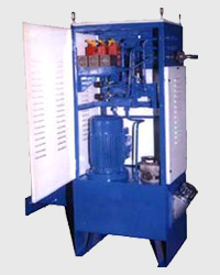
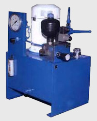
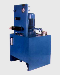
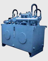
- Vertical & Horizontal Design
- Standard & Compact Design of Power Pack
- Precision Pump Mounting Adaptors in Bellow
- Remote Compensator ans Safety Relief
- 1400 RPM Motor
- Oil Level Gauge with Thermometer
- Breather and Fill Cap
- Glycerin Filled Pressure Gauge with Shut Off
- Submerged Pump
- Suction Strainer
- Cleanout Cover
- Drain Plug
- Standard & Compact Design of Power Packs.
- Best Pipes Fitting.
- Block Mounting or a Console Type.
- Suitable for different Application like Ceramics, Textiles, Foundries, Road Construction, Presses, Rubber Molding, Plastic Molding Machines, Machine Tools, etc.
|
|
|
|
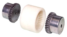
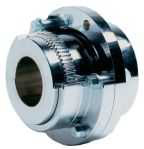
Dyna gear coupling has two steel gears which engage in a sleeve of high grade plastic material which has got very good strength over a wide range of temperature. The steel gears have curved top surface to allow for axial and angular misalignment. These coupling have been subjected to extensive testing under very severe conditions of leading. No lubrication or any other maintenance is required on this coupling. These couplings operate silently and can be installed easily.
ASSEMBLING PROCEDURE
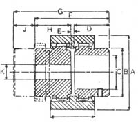
A maximum of 1.5 degree misalignment is permissible. The gears should fit easily on the shafts without requiring undue force. The gears can be secured to there respective shafts by means of grub screws. It is very essential to maintain a gap between the gears as shown in the sketch.
For shock load applications
Use the following formula : Rating/100 RPM of coupling = Hp of application x 100 x F/RPM of Application |
|
|
|
|
|
FACTOR F |
|
|
Application |
EI. Motor |
IC Engines |
Uniform Load |
1 |
1.2 |
Medium Shock |
1.25 |
1.5 |
Heavy Shock |
1.75 |
2.0 |
|
 |
|
|
|
|
Coupling
Size |
A |
B |
C
Max |
D |
E |
F |
G |
H |
J |
K
Min |
L |
Pilot
Bore |
DYNA 19 |
48 |
32 |
19 |
25 |
4 |
54 |
70 |
25 |
16 |
8 |
37 |
8 |
DYNA 28 |
66 |
44 |
28 |
40 |
4 |
84 |
104 |
40 |
20 |
10 |
46 |
10 |
DYNA 38 |
83 |
56 |
38 |
40 |
4 |
84 |
107 |
40 |
24 |
12 |
48 |
12 |
DYNA 48 |
100 |
68 |
48 |
50 |
6.5 |
104 |
126 |
50 |
22 |
20 |
50 |
16 |
DYNA 65 |
140 |
96 |
65 |
70 |
4 |
144 |
176 |
70 |
32 |
25 |
72 |
20 |
|
|
|