| FOR RELIABLE AND CONSISTENT PERFORMANCE |
|
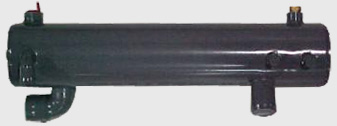
••• Multiple copper tube in a steel shell type construction using water as cooling medium.
••• Easily accessible tubes by opening the end cover.
••• Choked tubes can be easily cleaned or replaced in case of leakage. |
|
 |
CAPACITY
in Gallons |
A
(mm) |
B
(mm) |
C |
D
(mm) |
E(Sq.M.) |
F
(mm) |
G |
PT1
(BSP) |
PT2
(BSP) |
PT3
(BSP) |
SUITABLE FOR
max! h.p. |
5 |
485 |
450 |
20 |
16 |
.453 |
140 |
185 |
%" |
3/4" |
1/2" |
5 |
8 |
685 |
650 |
20 |
16 |
.654 |
140 |
185 |
3A" |
3/4" |
1/2" |
10 |
11 |
715 |
680 |
24 |
16 |
.820 |
165 |
225 |
1" |
1" |
1/2" |
12.5 |
17 |
915 |
880 |
24 |
16 |
1.062 |
165 |
225 |
1" |
1" |
1/2" |
15 |
21 |
1085 |
1050 |
24 |
16 |
1.27 |
165 |
225 |
11/4" |
1" |
1/2" |
20 |
28 |
854 |
800 |
44 |
16 |
1.771 |
216 |
275 |
11/2" |
11/4" |
3/4" |
25 |
38 |
1104 |
1050 |
44 |
16 |
2.324 |
216 |
275 |
2" |
1Y4" |
3/4" |
30 |
50 |
1304 |
1250 |
44 |
16 . |
2.77 |
216 |
275 |
2" |
11/4" |
3/4" |
40-50 |
60 |
1704 |
1650 |
44 |
16 |
3.65 |
216 |
275 |
21/2" |
11/4" |
3/4" |
60 |
|
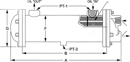
A- Over All Length B- Length of Copper Tube C- No. of Copper Tubes
D- Dia of Copper Tubes E- Total Cooling Area of Copper Tubes F- Diameter of the Shell
G- Diameter of the Flanges
|
PRINCIPLE OF OPERATION
The Oil to be cooled is admitted into the shell around the densely fitted copper tubes having a number of baffles which make the oil flow in a zig-zag manner. Oil gives out its heat to water that flows through the copper tubes having multiple path ways. This enhances contact time of water with oil for better heat transfer. This type of system makes the cooler highly efficient.
Working Pressure: 10kg/cm2. |